CNC Machining Design Guide Optimize your part design for cost and time savings.
Introduction
CNC Machining is a process by which material can be removed from pieces of stock with unparalleled repeatability, precision, and speed. Vertical milling machine, horizontal milling machines, and lathes are common machine tools tools used in CNC machining.
CNC machines are controlled by programs that dictate how they move. Parts are designed using CAD (Computer-Aided Design) programs, and CAD models are output. These models are then imported into CAM (Computer-Aided Manufacturing) programs, and tool paths are generated. Tool paths tell a CNC machine how to move and what tool to use, such that material is removed in the most efficient manner.
The complexity of the part dictates what CNC machine should be used. For cylindrical parts, a CNC lathe might be best. For simple 2D geometry, a 3-Axis milling machine would be perfect. You as the designer can make decisions when creating you part that aid the manufacturing process. The intent of this guide is to familiarize you with the limitations of CNC machines.
General Tolerances
General Tolerances
If the customer has not provided a part drawing with their CAD model, Swift Parts will follow a standard set of rules when manufacturing the part. These rules can be referenced below-
- Sharp edges resulting from the machining process with be deburred by default. If it is desired that an edge remains sharp, the customer must note that in a part drawing.
- A tolerance of +/- 0.005” will be applied to all size and location features (Length, width, height, diameter, position, concentricity, symmetry).
- For parts 0-12” long, orientation and form (parallelism, perpendicularity, cylindricity, flatness, circularity, and straightness) tolerances will be kept to .005”. Angularity will be kept to +/- .5 degree.
- For parts 12-24” long, orientation and form tolerances will be kept to .010”. Angularity will be kept to +/- .5 degree.
Part Tolerances
Tolerance is the permissible limit or limits of variation for a dimension of a part. These limits are usually chosen to ensure the fit and function of a part. Swift parts will assume a standard tolerance of .005” for metal parts and .010” for plastic parts. Tighter tolerances can be accommodated, but must be called out on a part drawing.
Tighter tolerances typically increase the cost of a part, due to the need for the machinist to spend more time or material ensuring the tolerance is met. The machinist might design special fixturing, use special tooling, or increase cycle times to increase precision. Only use tighter tolerances when necessary to reduce cost.
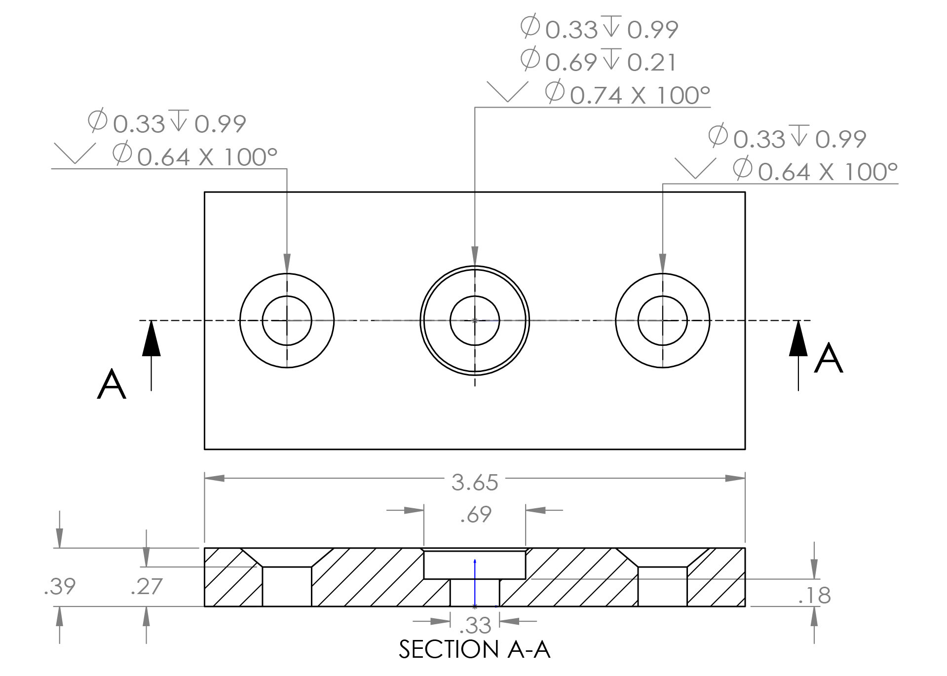
Image A -A part drawing featuring non-standard tolerances.
Part Size - Limitations and Pricing
As of now, Swift Parts’ machines have travel limitations of 30” (X) by 16″ (Y) by 20” (X). Parts must be able to fit within that volume to be produced. Please note that as parts approach maximum size, they will increase in cost non-linearly. This is due to the need for special fixturing and tooling to accommodate larger sizes.
Parts larger than 30”x16”20” can be made through Swift Parts, but will carry an increased cost due to the individualized nature of production.
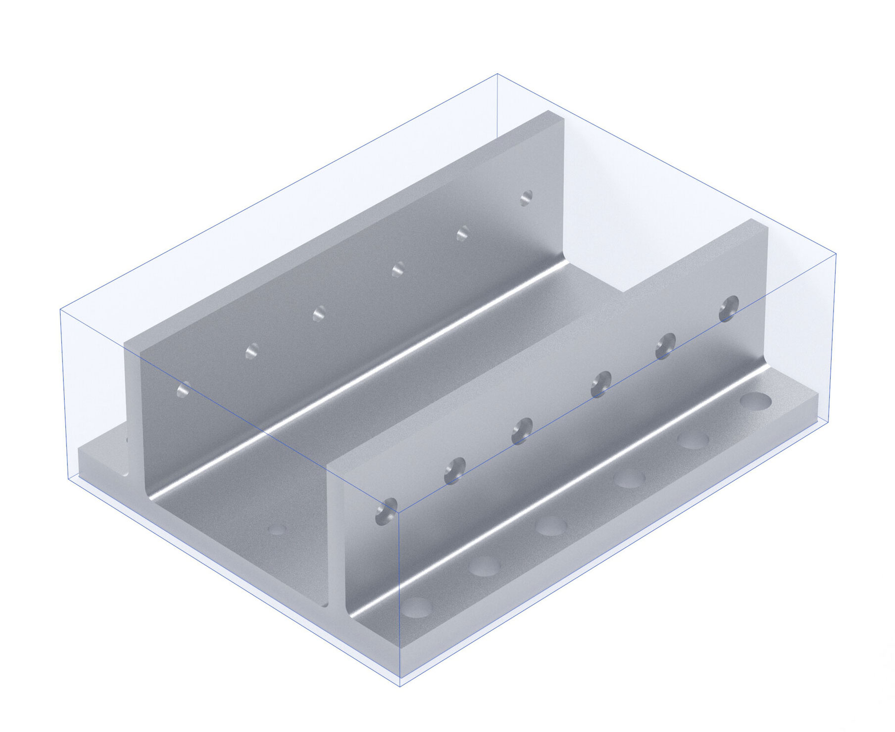
Image B - A large part near the travel limitations of Swift Parts.
Very small parts (smaller than 1”x1”x1”) will also begin to increase in cost. This is due not only for the need for special fixturing, but also due to the increased care machinist must make when loading the parts in the machine and when removing material with cutting tools.
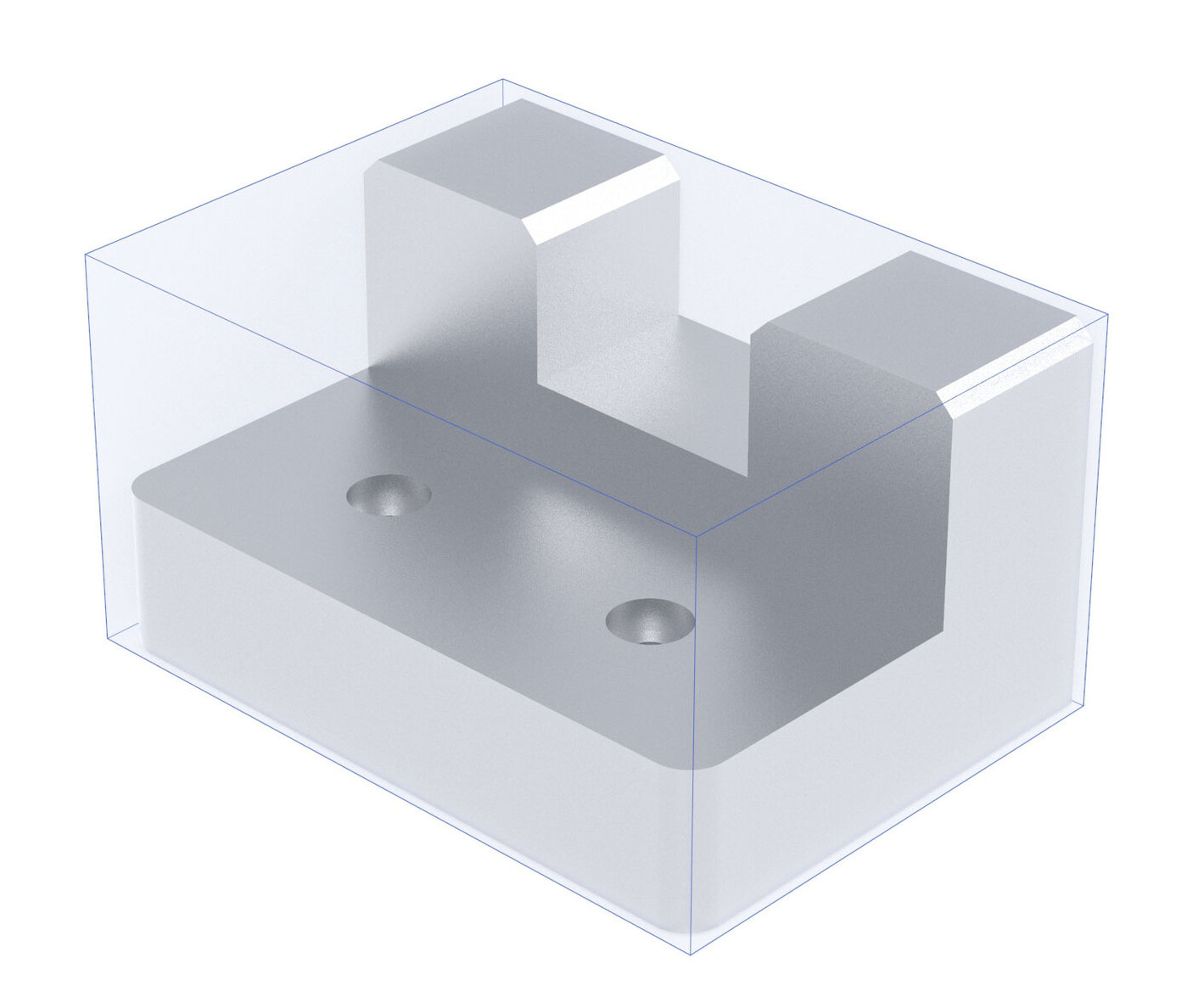
Image C- A small part less than 1”x1”x1” in size.
3 Axis or 5 Axis?
The two most common types of vertical machines are 3-Axis Machines and 5-Axis machines. As their names imply, 3 and 5 axis machines differ in the number of axes they utilize. 3-Axis machines can move cutting tools along the X, Y, and Z directions to shape a part. 5-Axis machines move along the X, Y, and Z directions as 3-Axis machines do, but also add two more axes, A and B, around which the tool rotates. This allows 5-Axis machines to access more of the part and to cut the part at more angles than 3-Axis machines.
While 5-Axis machines offer increased performance vs. 3-Axis machines, parts produced on them can also require more stock material and more setup time. The sections below help illustrate the differences between 3 and 5 Axis machines, and provide insight as to when a part might require one or the other.
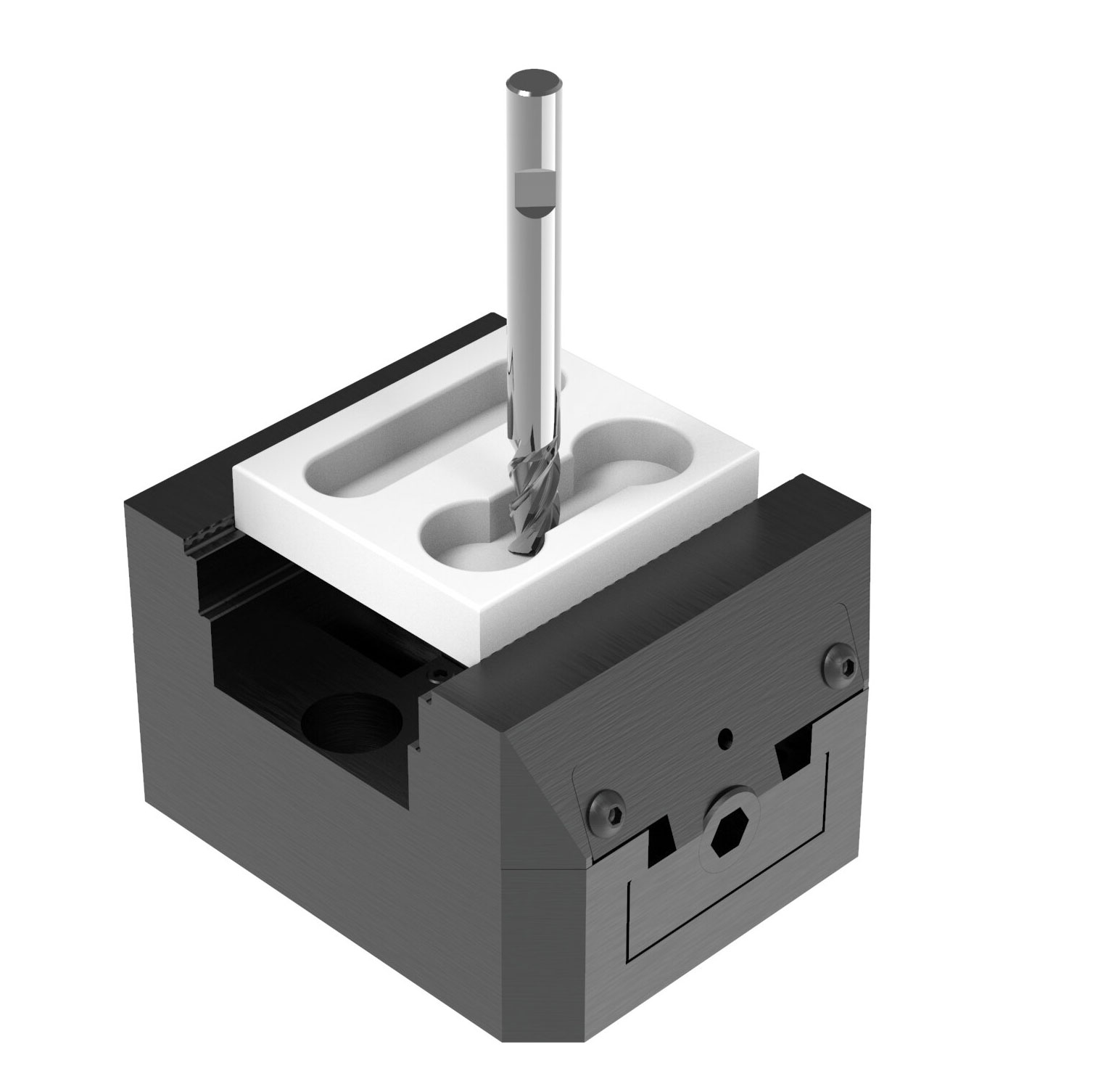
Image D - With 3-Axis machines, the tool comes down perpendicular to the table on which the part is loaded.
3 Axis
With a 3-Axis machine, the tool cuts perpendicular to the table on which the workpiece is mounted. 3-Axis machines are great at cutting pockets, profiles, and other geometries that feature walls that are perpendicular to the cutter.
More complicated and organic surfaces can also be cut on 3 Axis machines. however in order to achieve this, very small cuts must be made. These small cuts take significantly longer to produce than cuts based on perpendicular or parallel plane geometries, and as such raise the total part cost.
In order to save machining time by reducing the number of tool changes, design parts with consistent internal radii and hole diameters when possible.
Special features like undercuts (see section below) can sometimes be created on 3-Axis machines, but will increase cost due to the need for special tools and operations. Some undercuts are impossible to machine, regardless of whether a 3 or 5 axis CNC is used.
5 Axis
With 5-Axis machines, a part can be rotated about two Axes, A and B. This allows for the tool to mill perpendicular to the top of the part, the side of the part, or any angle in-between.
5-Axis machines allow for the machining of features that are either difficult or impossible to produce on 3-Axis machines. In the graphic shown at the right, you can see endmills interacting with parts from all angles. This allows for the creation of undercut features or diagonal surfaces with relative ease. The drill creating a hole at a 45 degree angle to the top of the part could not be produced on a 3 Axis machine without time consuming fixturing and setup.
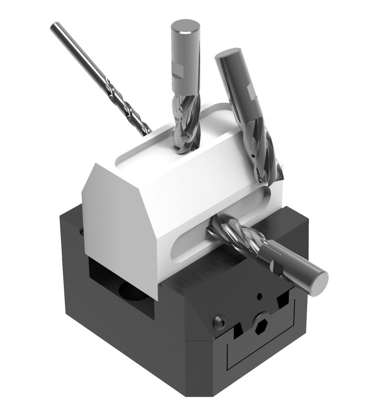
Image E - With 5-Axis machines, the part can be rotated along 2 new axes, allowing the cutting tool to interact with the part from new angles.
UNDERCUTS
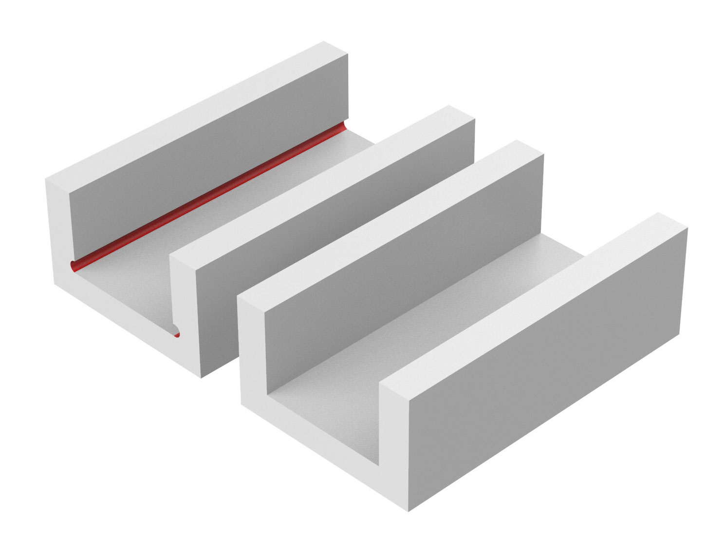
Image F - Two parts, one with an undercut (shown in red) and one without.
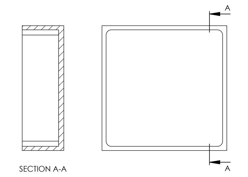
Image G - A cross section of the part from Image J with inside corner fillets.
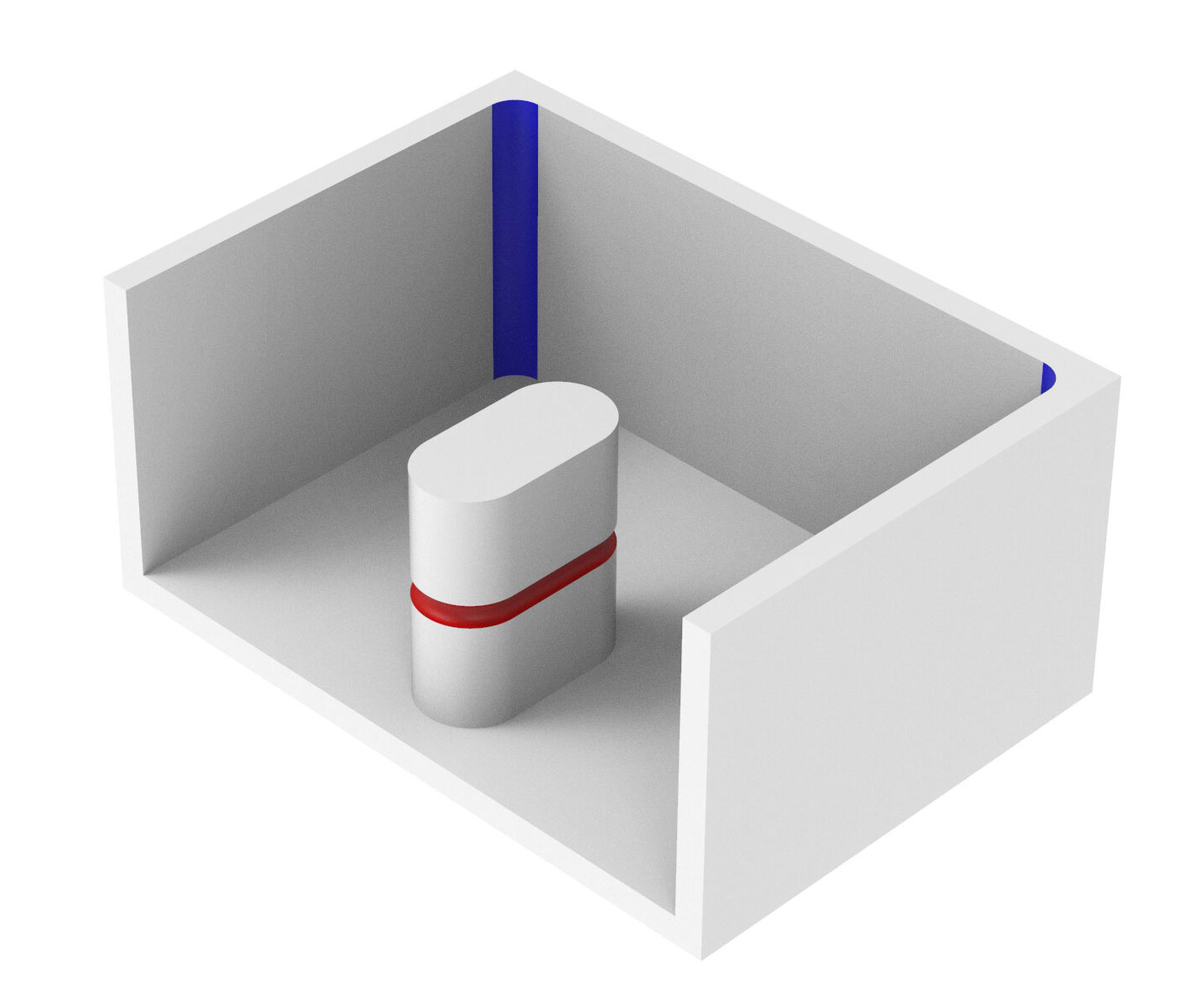
Image H - An additional part with an undercut (shown in red).
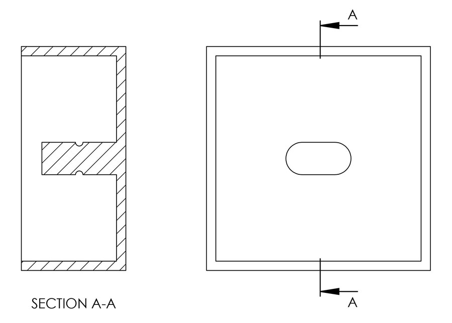
Image I - A section view of the part shown in Image H.
Some features in a model cannot be machined using standard tooling (endmills, drills, reamers, etc.). This phenomenon, when it manifests in the way shown in Images F through I, is called an undercut. Undercuts are costly and difficult to machine for the following reasons:
First, if the feature cannot be created with standard tools, it will necessitate the creation of a custom tool. Custom tools are time consuming and expensive to make, and could cost several times what a standard tool does. Say for example that the undercut shown in Images H and I had a radius of .047”, a custom tool would need to be made. Money could be saved by designing the part with an undercut radius of .062”, or by eliminating the undercut feature altogether.
Second, if the undercut is too “deep” into the material, it may be difficult or even impossible to machine. The more shallow an undercut the better.
INTERIOR FILLETS
When using a CNC machine, all internal vertical walls on a part will feature a radius. This is due to the fundamental nature of how CNC machines remove material. Material is cut away using a round tools spinning very quickly. Parts must take into account this limitation.
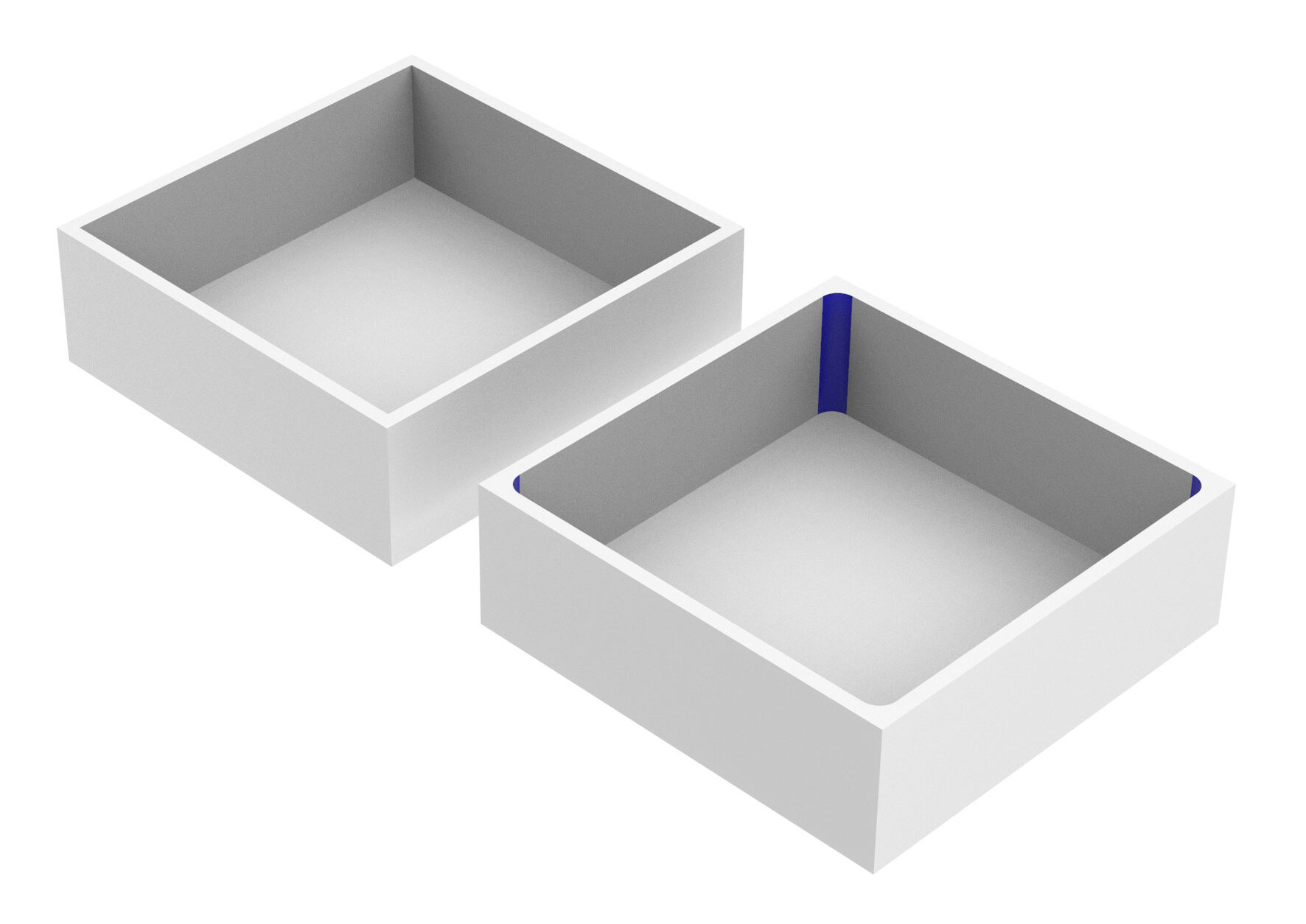
Image J - Two parts, one with an inside corner fillet (the blue surface) and one without.

Image J - A cross section of the part from Image J with inside corner fillets.
INSIDE CORNER FILLETS
For inside corner fillets, it is desirable to use a nonstandard radius. This is because endmills perform better when their radius is smaller than the fillet they are cutting, allowing them to turn and continue milling in one continuous motion.
For example, say the internal fillet feature of the part shown in Image J had a radius of .25”. In this case a .5” diameter endmill would need to come to a complete stop in the corner of the vertical walls, then shift direction. This increases machine time, and produces vibration which can impact surface finish. If the feature radius was increased to .30”, or even .27”, it would allow the endmill to “roll through” the corner without stopping completely, increasing the speed of the operation and improving surface finish.
Use the largest radius possible for inside corner fillets. Larger radii allow for larger tools to be used, which can dramatically increase the speed at which the machine cuts.
Though small cutting tools are available to create small inside corner fillets, at some point the ratio of the diameter of the cutting tool to the length of cut becomes too small. A tool with a very long cutting length (called flute length) relative to the tool diameter can not only be expensive, but is also more likely to break or cause “chatter”, which can negatively impact surface finish.
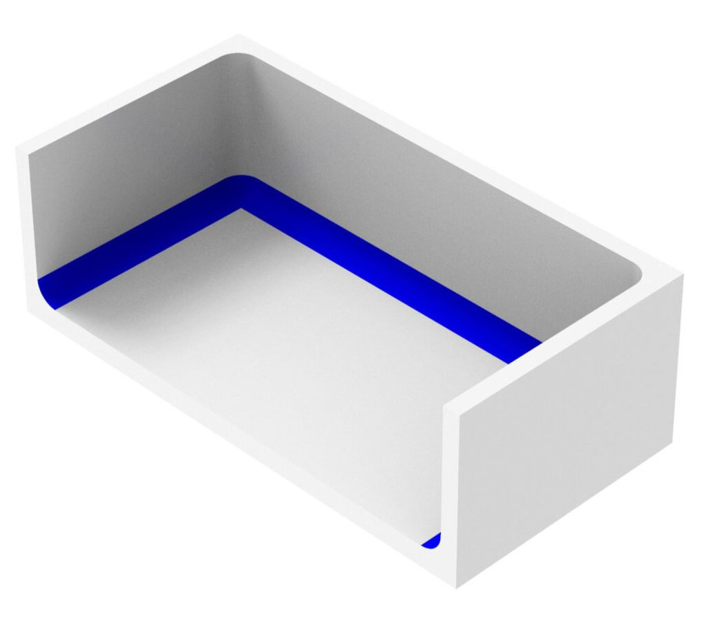
Image K - A part with floor fillets, highlighted in blue.
Also note the vertical wall fillets.
FLOOR FILLETS
Floor fillets, as shown in Image K, are features that can be added to a design to increase strength. They also sometimes allow for more robust endmilles to be used; instead of coming to a sharp point at their corners, these endmills have rounded corners, which increases tool life. When designing parts with floor fillets, be careful to make the floor fillets’ radius smaller than the wall fillets’ radius. Additionally, try to use floor fillets that increase by intervals of 1/16”. This will allow standard endmills to cut the floor fillets in one pass.
DRILLING
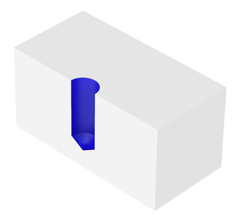
Image L - A hole drilled in a piece of material.
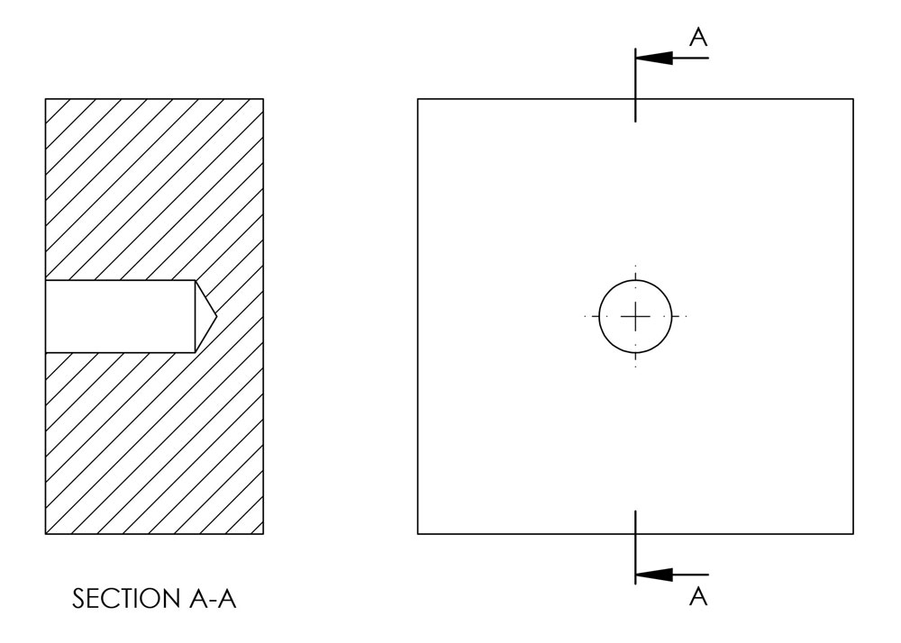
Image M - A cross section of the part from Image L.
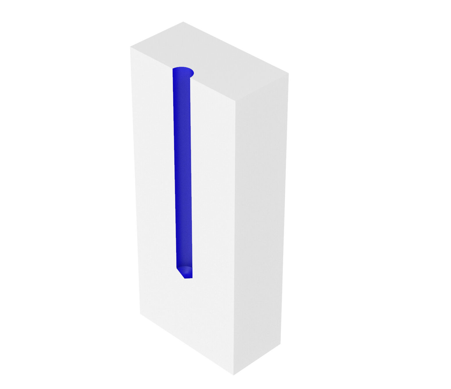
Image N - A deep drilling operation in a part.
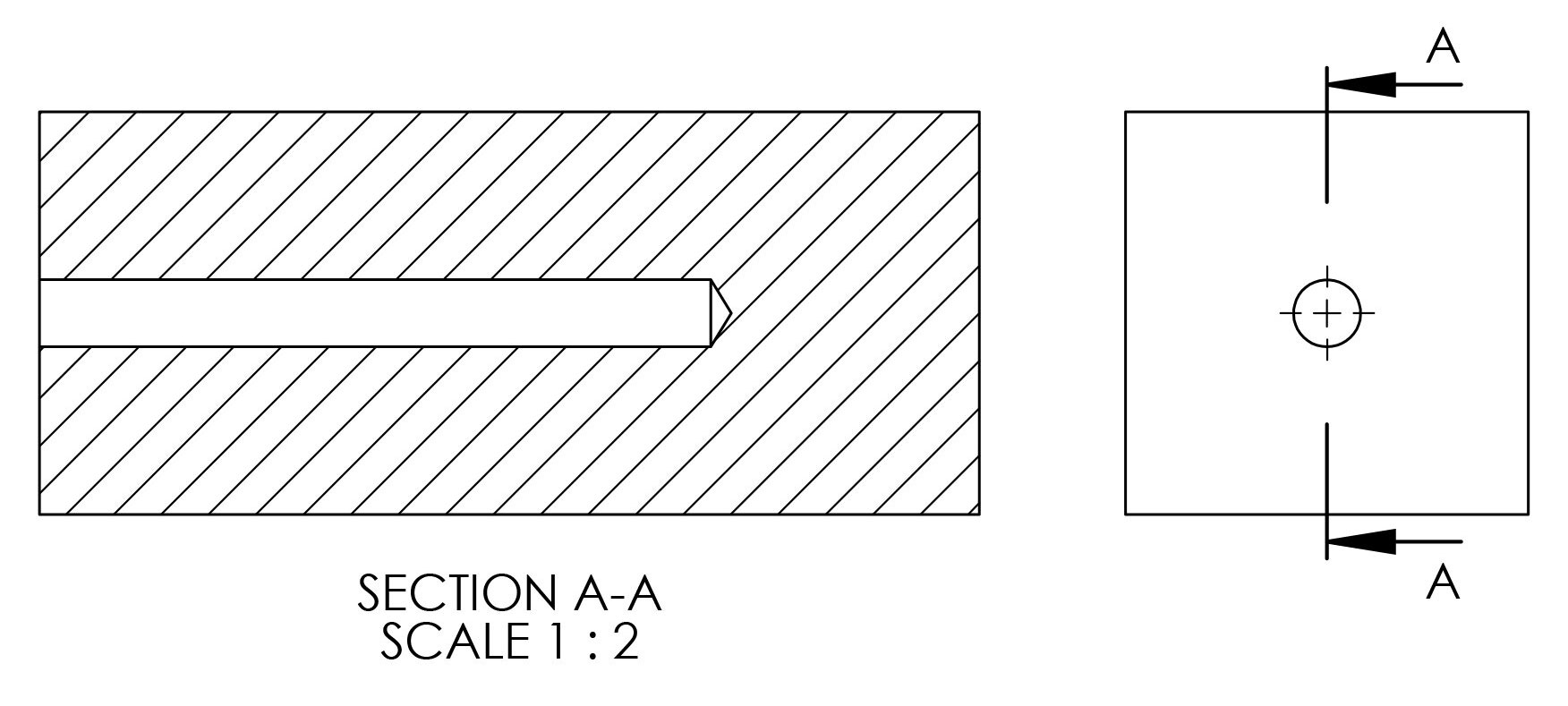
Image O - A cross section of the part from Image N.
Holes can be created on a part using a drill bit. Drill bits offer a cheap and time effective way to create holes. If very tight tolerance holes are required, drills can be followed by reamers.
Deep drilling is a process by which a hole with a length of 10X (or more) its diameter might be created. Deep drilling is a more difficult process to achieve compared to normal drilling, and as such carries with it an increased cost. Special tools and setups are required to deliver coolant, evacuate chips, and create depth-to-diameter holes beyond what standard drilling operations can reach.